| Wiring | ||
| HOME
|
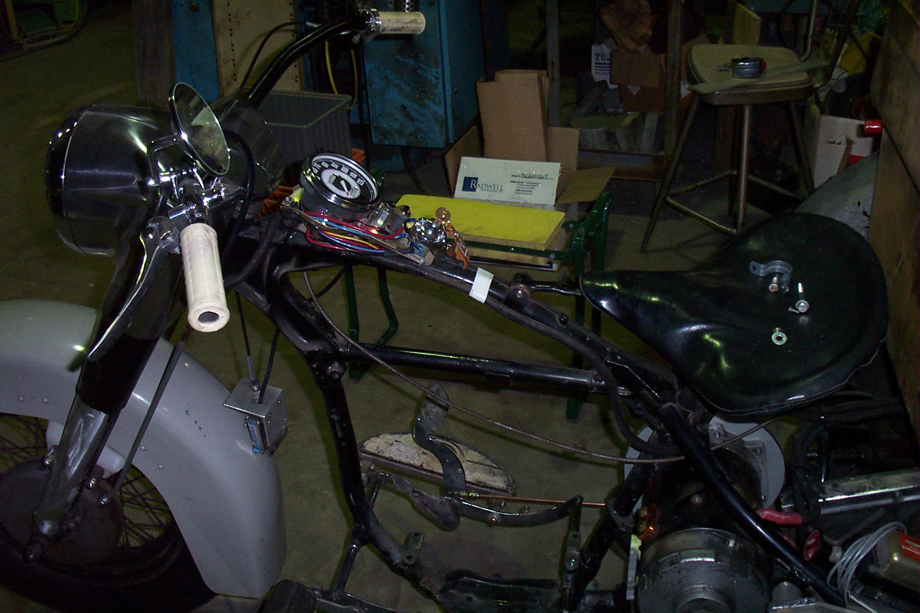
Now on to the wiring.
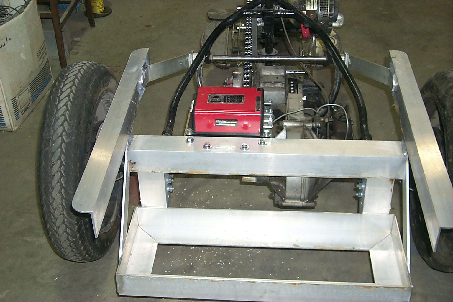
After looking at the bike for a while I think I have located a good place for the speed control to mount which will make a clean project and be out of the way. I am using a SRE PC325 made by Navitas Controls out of Canada. This was purchased for a forklift upgrade that never happened several years ago. It is designed as a pump control for the lift pump on a forklift and is rated at 325 amps continuous and 1000 amps peak. Fortunately, it is set up for a speed pot as well as several set speed inputs.
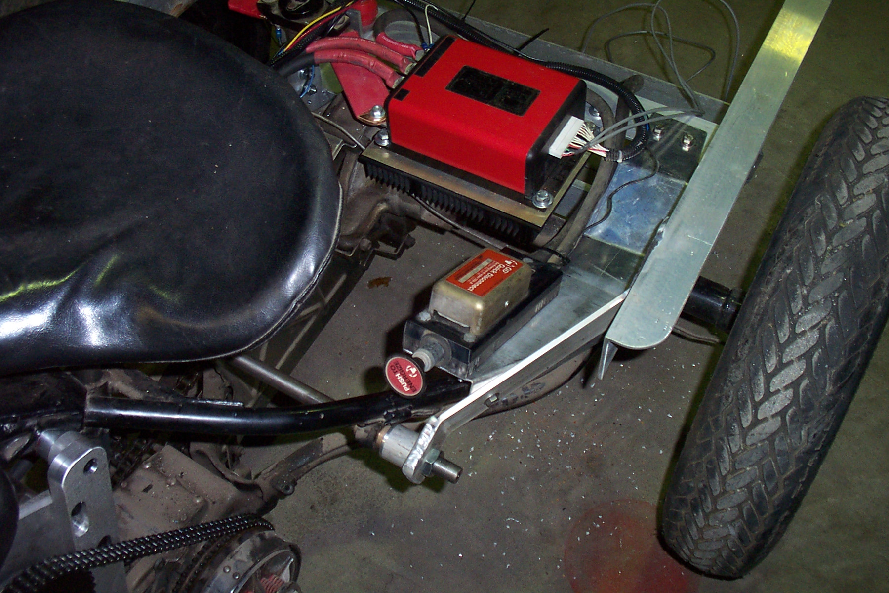
Here it is mounted on a heat sink that I had removed from a military surplus lot of material. This location is below the level of the box "floor" and between the battery rack and the motor.
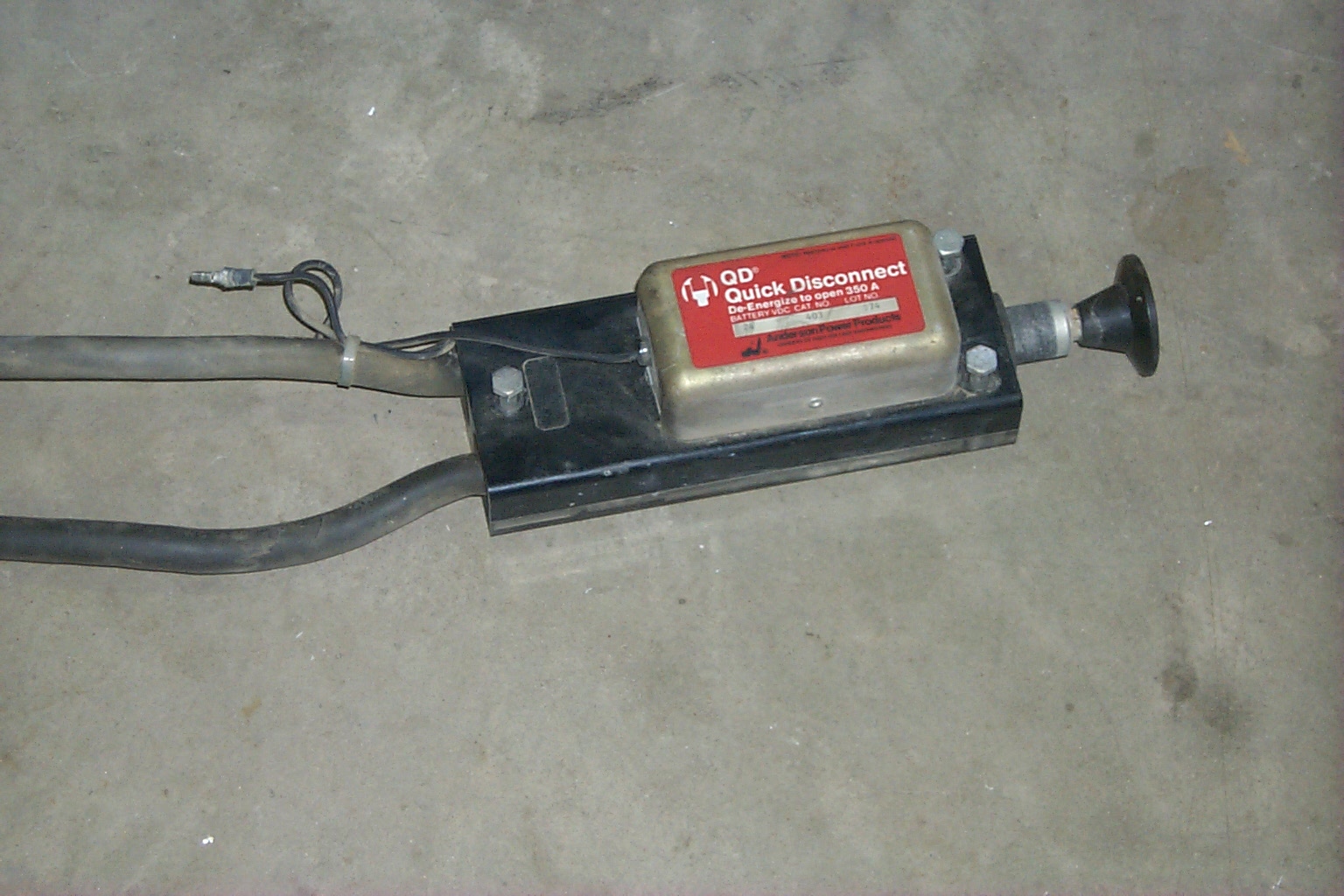
I also retrieved from the pallet picker an emergency kill switch which I am still thinking about where to locate on the bike. The kill switch is remote controlled and rated at 350 amps. Since it was on the pallet picker that the motor came off of it should be capable of killing the motor circuit if required.
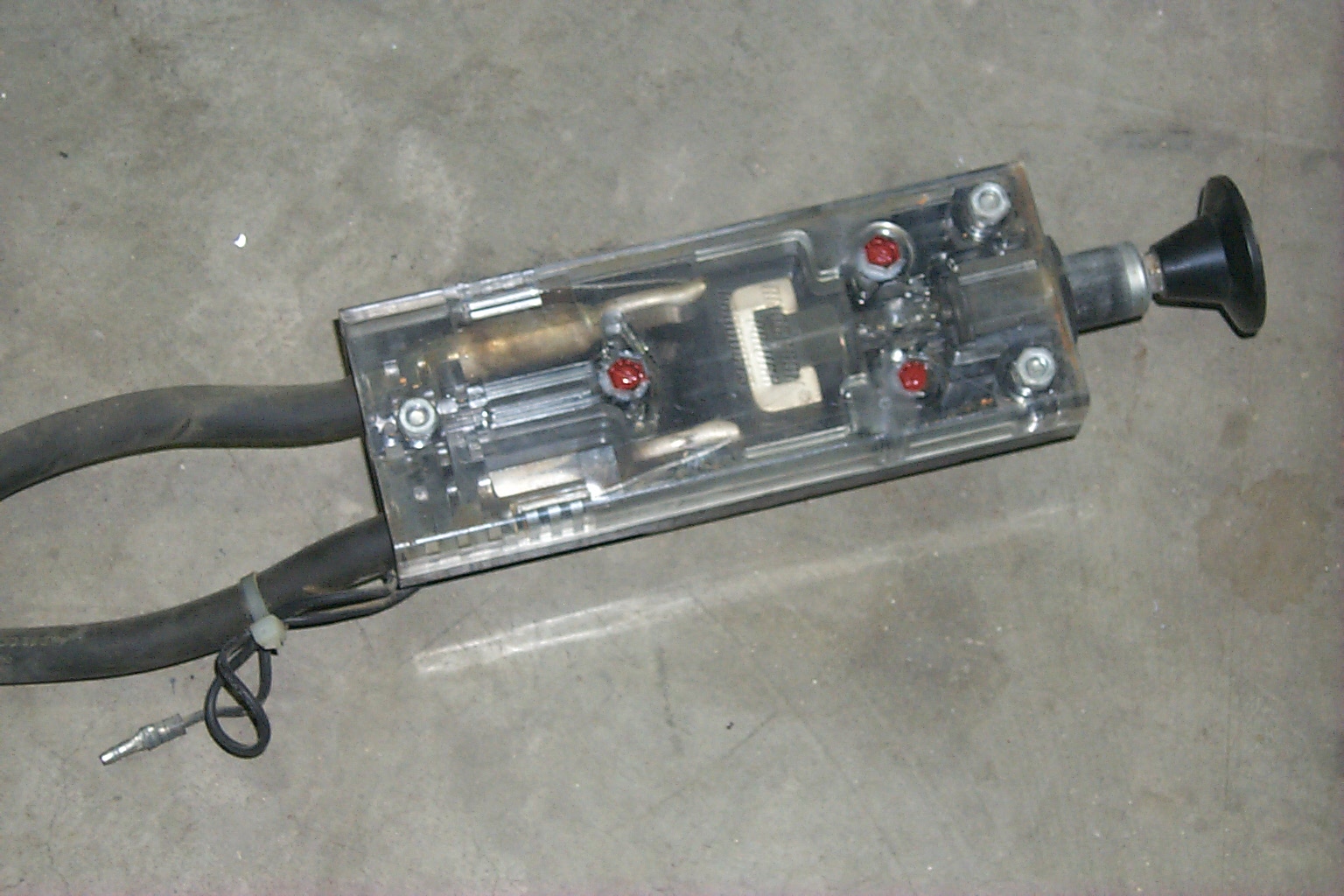
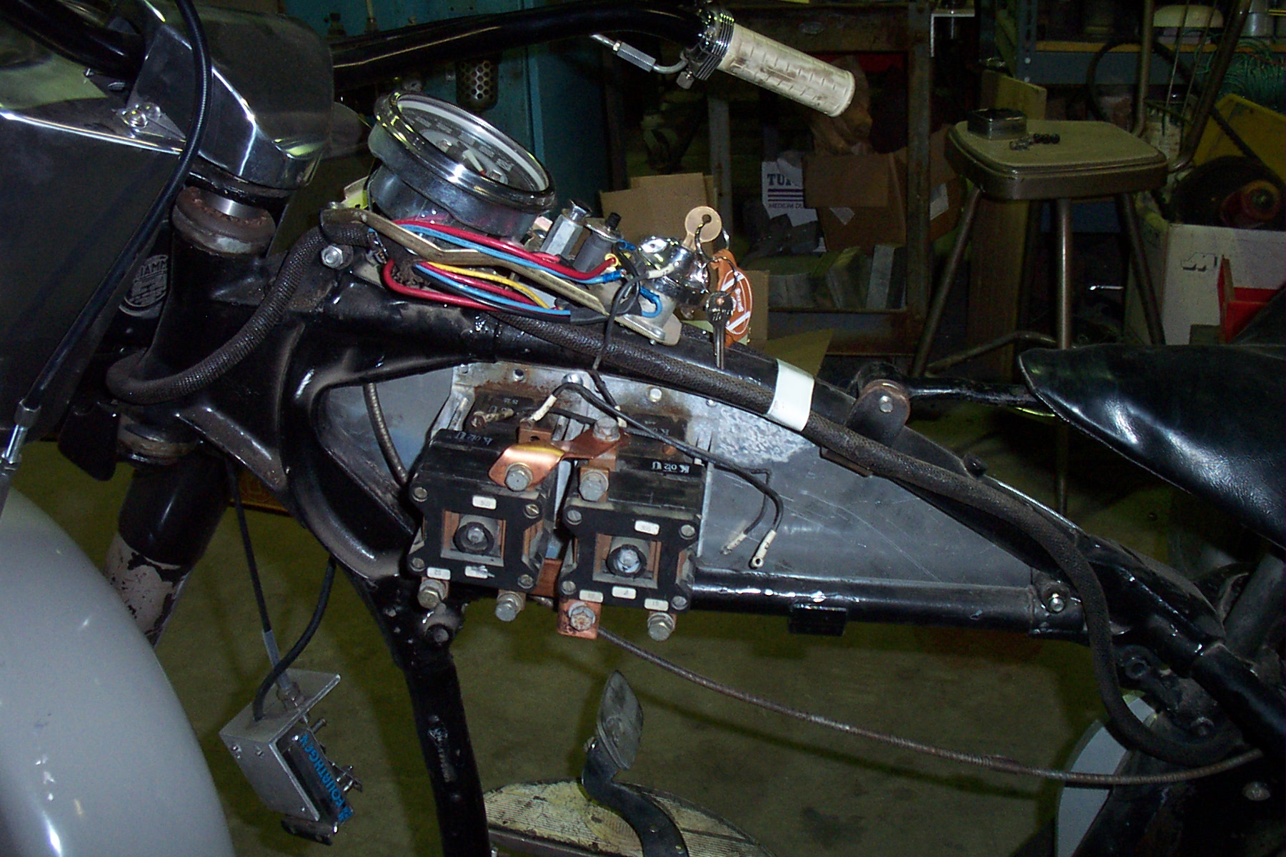
These are pictures of the emergency "Quick Disconnect". The small wire is the control circuit which must be on for the switch to remain engaged. The black knob on the right must be pushed in manually to reset the switch every time the power is cycled. A slight problem has come up with the power relays that I have been intending to use from the pallet picker as they appear to have 18 volt coils. I have posted a question to the gurus on the EVDL to see what I can do about this little hitch. The call on the EVDL came up with a couple of ideas. First use a simple resistor in series with the coil sized to drop the additional 6 volts. Second build a slightly more complicated circuit with a driver integrated circuit (IC) to power the coil at the required voltage. A new tack and an inspiration have come up with a different relay to use for the power relay which eliminated the need for an 18 volt signal. I remembered the main power relay that used to be on a zoom boom manlift that I had converted to solid state control many years ago. It originally used an aircraft starter relay to switch on and off the motor, but it had been removed when the lift was made electronic with a Curtis controller. Being a packrat, I had saved the removed relay and also the spare relay that I had for the manlift. They are rated at 400A DC on the power pole and 28 volts DC continuous on the coil. On the manlift they had been run on the 24 volt control circuit. A quick test on the bench power supply showed it to work fine on 24 volts.
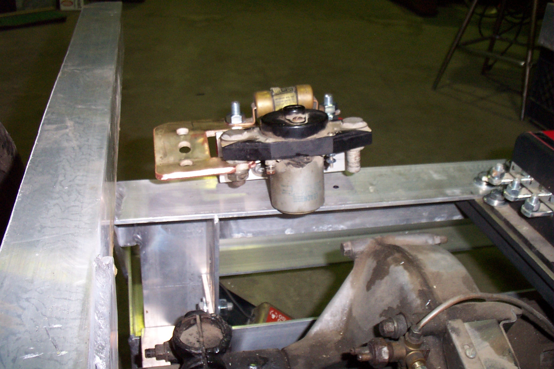
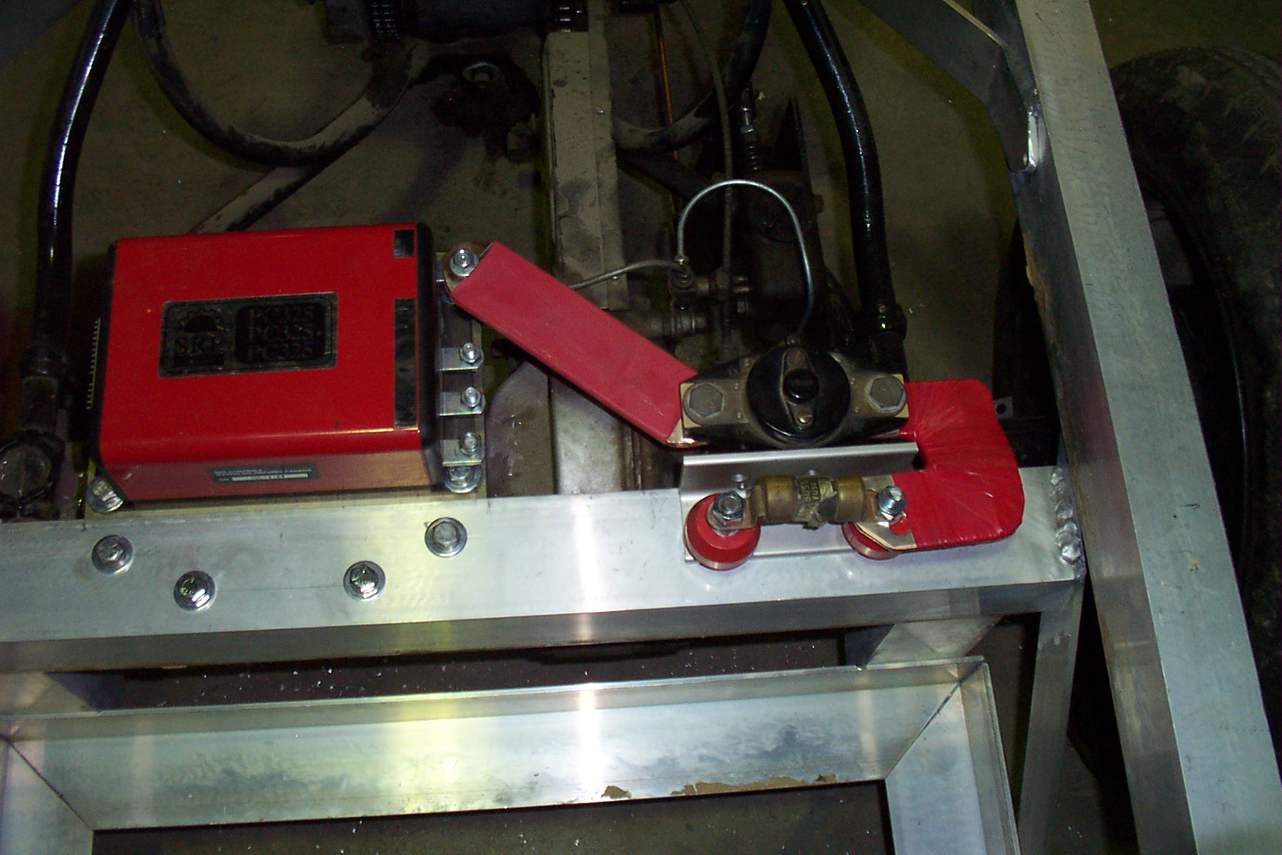
This is the power relay from the manlift. The fuse and buss bar were not a part of the manlift. I located a mounting place next to the speed controller where I can make the connection to the B+ on the controller with a piece of copper buss bar. I was able to mount the power fuse on a pair of insulators commonly called "red apples" in the trade. In my pile of old buss bars from motor control centers I was able to locate a "U" shaped piece that I was able to modify to connect the output of the power fuse to the input of the power relay.
This makes a really compact installation for the + side of the power circuit. The left side of the power fuse in the above picture will be cabled to the + side of the battery pack. I was able to use a piece of shrink tube to insulate the bar going from the power relay to the controller. The buss from the fuse to the power relay had to be insulated with tape since it is wider than the largest shrink tube that I have. I used a layer of varnished cambric covered by a double layer of vinyl tape. I have gotten the Emergency Disconnect mounted and begun the wiring.
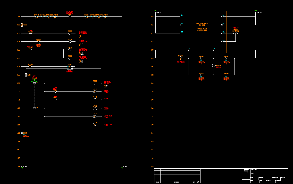
This location will put the operator handle just out from under the front of the back box and under the riders seat. It should be easy to reset when mounting the bike. I intend to mount a maintained position pushbutton on the dash to use as an emergency stop switch as well as having the control through the key switch. Here is the preliminary sketch of the wiring. The system will be very simple with no turn signals or marker lights. Only a head light, tail lights and stop lights. The power wiring is now done and I have moved on to the controls.
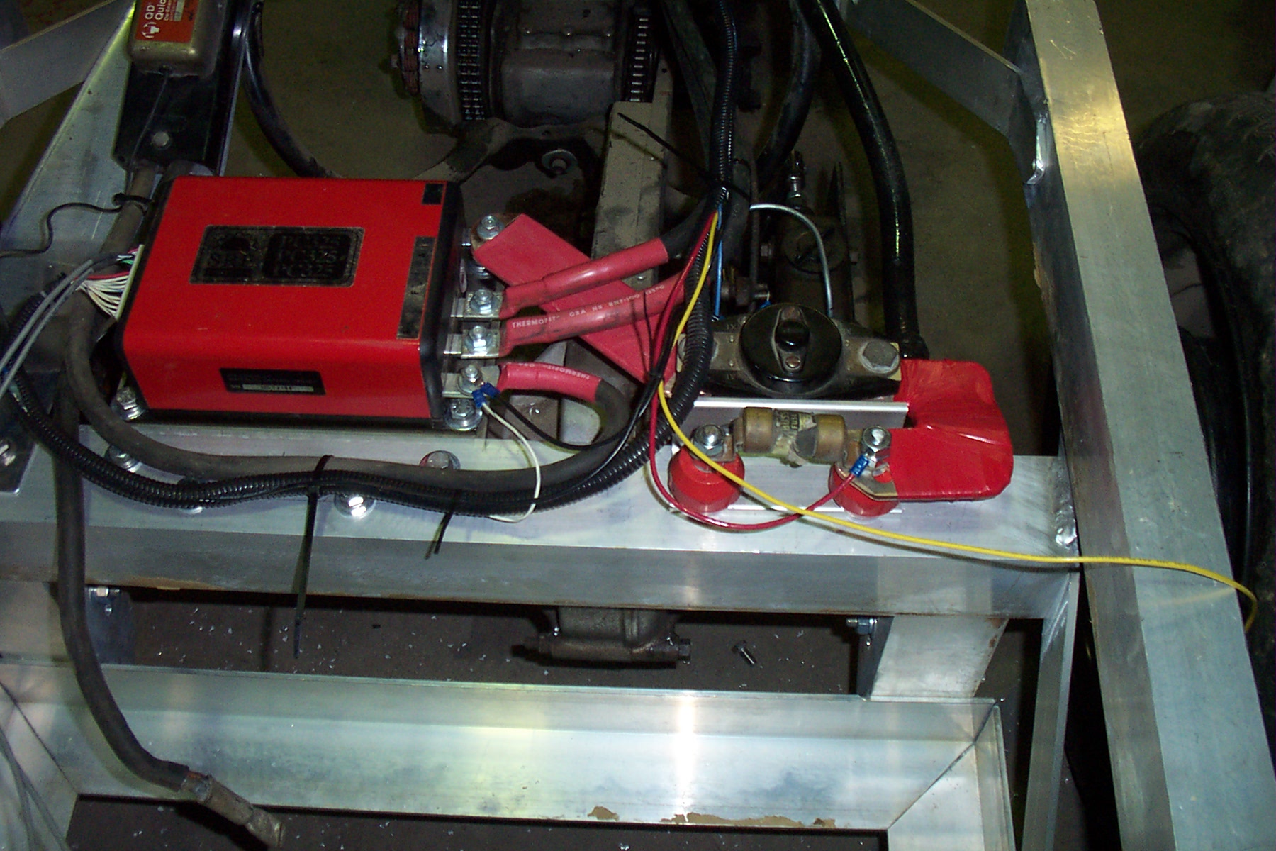
The wire from the emergency disconnect had a lug already mounted on it and it was long enough to reach to the B- terminal on the controller. I added the shrink tube to keep the exposed metal to a minimum. I don't have large enough shrink tube in any color but red so all the power lugs are insulated red. As shown in the picture, the shrink tube was installed long enough on the leads to the motor to go beyond the B+ power bar just for an added measure of insulation. The wires are also separated by an air gap, but time may allow them to close the gap. All that is left of the power wiring is the batteries and battery interconnects. I need to make a trip to Sacramento tomorrow and may be able to pick up some batteries there. It is probably a little premature, but I want to try the system to see how it will move the bike. The control wiring is begun and the yellow wire shown off the side of the picture above is for the tail lights. With a 24 volt system I am going to install the tail and stop lights in series to allow 12 volt lamps to be used. If I decide to increase the battery voltage to something higher, then I will have to install a DC-DC converter to create the 24 volts for controls and lighting.
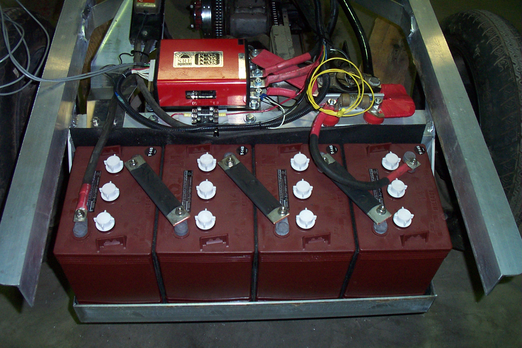
Above are the first 4 batteries installed in the battery rack as well as a shot of the interconnect. The interconnect is made out of copper buss bar and insulated with shrink tube. All bolts were torqued to the manufacturer's spec of 95-105 inch pounds. June 06; As noted on the drive page, I have removed the transmission and now need to add an electrical reverse. I don't want to destroy the original gas and oil tanks for the bike as they are vintage and in good shape. I did find a set of other tanks that I am planning on cutting the back out of to make a cover for the new electrical reverse.
I was able to use a piece of .125" aluminum to make a mounting plate that mounts on the existing tank mounting holes. I am also able to mount the throttle pot on the back side of the plate and get it hidden inside the other tank as well.
The photo on the left is the trial fitting and on the right is mounted and the power wiring installed. I used parts from some of the additional relays on the pallet picker to beef up the contacts on the forward portion of the relay as the original contacts were about a .375" diameter contact pad and the other relays had almost .625" pads. I used some copper buss bar to connect the two relays together and have wired it such that the forward direction is with both coils de-energized. I am planning on using a single push button to energize both coils when I need to go in reverse. The coils are rated 24 intermittent and 18V continuous. I don't plan on running in reverse for more than a few seconds at a time so I am going to try using power from the 24V control portion of my design. Here is a clean drawing of the wiring as I have it planned for the bike.
By using the odd tanks that I have, I will be able to install the fuel gauge and probably an ammeter into the top of the tank. The ammeter is not incorporated into the drawing now and will have to be added as a shunt in the motor loop somewhere. It might be able to be mounted adjacent to the reversing contactor and have a very short run to the meter. I haven't gotten a design figured out yet to mount the "tanks" but when I do, it will be on the bodywork page. |